Geometric Dimensioning and Tolerancing (GD&T) is a complex system used to define and communicate the engineering tolerances of a part or assembly. It is widely used in various industries, including aerospace, automotive, and medical devices. Despite its importance, many engineers and designers find GD&T challenging to apply and interpret. In this article, we will simplify the application and interpretation of GD&T, making it easier for you to understand and use.
What is GD&T?
Geometric Dimensioning and Tolerancing is a system of symbols, rules, and definitions used to define the allowed variation in the size, shape, and location of features on a part or assembly. It provides a common language for engineers, designers, and manufacturers to communicate the tolerances of a part, ensuring that it meets the required specifications.
Why is GD&T Important?
GD&T is essential in ensuring the quality and functionality of a part or assembly. By defining the allowed variation in size, shape, and location, GD&T helps to:
- Ensure interchangeability of parts
- Reduce manufacturing costs
- Improve product quality
- Enhance safety and reliability
Basic Concepts of GD&T
Before we dive into the application and interpretation of GD&T, let's cover some basic concepts:
- Datum: A datum is a reference point, axis, or plane used to establish the orientation and location of a feature.
- Feature: A feature is a geometric element, such as a surface, edge, or axis, that is used to define the shape and size of a part.
- Tolerance: A tolerance is the allowed variation in the size, shape, or location of a feature.
- Zone: A zone is a region within which a feature must be located or oriented.
GD&T Symbols
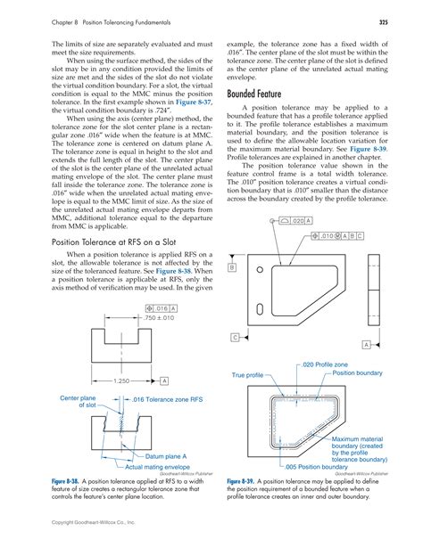
GD&T uses a set of symbols to define the tolerances of a feature. These symbols are used in conjunction with the feature control frame, which is a rectangular box that contains the tolerance information.

Feature Control Frame
The feature control frame is a rectangular box that contains the tolerance information. It consists of several elements, including:
- Feature symbol: The feature symbol indicates the type of feature being controlled, such as a surface or axis.
- Tolerance value: The tolerance value indicates the allowed variation in the size, shape, or location of the feature.
- Datum reference: The datum reference indicates the reference point, axis, or plane used to establish the orientation and location of the feature.
- Zone: The zone indicates the region within which the feature must be located or oriented.

GD&T Rules
GD&T has several rules that govern its application and interpretation. These rules include:
- Rule #1: The tolerance zone must be defined in relation to a datum reference.
- Rule #2: The tolerance zone must be defined in relation to a feature symbol.
- Rule #3: The tolerance value must be indicated in the feature control frame.
Interpretation of GD&T
Interpreting GD&T requires a thorough understanding of the symbols, feature control frame, and rules. Here are some tips for interpreting GD&T:
- Read the feature control frame carefully: Pay attention to the feature symbol, tolerance value, datum reference, and zone.
- Understand the datum reference: Identify the reference point, axis, or plane used to establish the orientation and location of the feature.
- Visualize the tolerance zone: Imagine the region within which the feature must be located or oriented.
Application of GD&T
Applying GD&T requires a thorough understanding of the symbols, feature control frame, and rules. Here are some tips for applying GD&T:
- Use GD&T to define the tolerances of a feature: Use the feature control frame to define the tolerance value, datum reference, and zone.
- Use datum references to establish the orientation and location of a feature: Use datum references to establish the orientation and location of a feature.
- Use zones to define the region within which a feature must be located or oriented: Use zones to define the region within which a feature must be located or oriented.
Common GD&T Applications
GD&T is widely used in various industries, including:
- Aerospace: GD&T is used to define the tolerances of aircraft and spacecraft components.
- Automotive: GD&T is used to define the tolerances of automotive components, such as engine blocks and cylinder heads.
- Medical devices: GD&T is used to define the tolerances of medical devices, such as surgical instruments and implants.
Gallery of GD&T Applications


FAQs
What is GD&T?
+Geometric Dimensioning and Tolerancing (GD&T) is a system of symbols, rules, and definitions used to define the allowed variation in the size, shape, and location of features on a part or assembly.
Why is GD&T important?
+GD&T is essential in ensuring the quality and functionality of a part or assembly. It helps to ensure interchangeability of parts, reduce manufacturing costs, improve product quality, and enhance safety and reliability.
What are the basic concepts of GD&T?
+The basic concepts of GD&T include datum, feature, tolerance, and zone. A datum is a reference point, axis, or plane used to establish the orientation and location of a feature. A feature is a geometric element, such as a surface, edge, or axis, that is used to define the shape and size of a part. A tolerance is the allowed variation in the size, shape, or location of a feature. A zone is a region within which a feature must be located or oriented.
In conclusion, GD&T is a complex system that requires a thorough understanding of its symbols, feature control frame, and rules. By applying and interpreting GD&T correctly, engineers and designers can ensure the quality and functionality of a part or assembly. We hope this article has simplified the application and interpretation of GD&T, making it easier for you to understand and use.
